Valves must be sized correctly in accordance with the system requirements to ensure proper and stable operation throughout the full range of flows required for refrigeration loading and condenser water temperature conditions. Proper sizing is determined by maximum required condenser water flow rate and available pressure drop (available pressure to push the water through the valve). The following steps should be taken in sizing and selecting a valve for normal installations:
1. Determine the water flow required at maximum load conditions. The maximum water flow is usually specified by the condenser manufacturer. If this information is not readily available, a good “rule of thumb” is 3 GPM water per ton of rated refrigeration capacity, assuming 85°F maximum tower water conditions. If the water temperatures vary significantly from these numbers provided, a typical value’s required water flow can be calculated as follows:
- Determine the maximum load conditions, i.e., the maximum BTU’s/hour to be removed. It is important to add heat gains from refrigeration equipment and the heat of compression. If these figures are not available, it is customary to add 25% to the load.
- Determine the incoming water temperature at the time of maximum load.
- Determine the outlet water temperature, which must be less than the condensing temperature of the refrigerant and can be found in the condensing unit manufacturer’s data. If this value is not available, assume 10 °F above inlet temperature.
- Required Water Flow (GPM) =

NOTE: TEMPERATURE IN F°
2. Determine the pressure drop available for the valve. The value should be selected to provide required maximum rated flow at a pressure drop that is acceptably low in comparison the pressure drop that is available from the system.
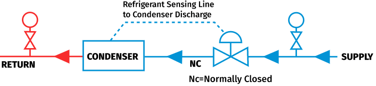
The available pressure drop can be described generally as the Supply Pressure, minus the Sum of the Pressure Losses between the Supply and Return sources, minus the Return (to tower) Pressure at rated maximum flow. Important note: all pressures and pressure drops should be determined or calculated at rated maximum flow. Specifically:
- The Supply Pressure is taken from the outlet of the pump providing the water or from the water supply pressure.
- Subtract the pressure drop in the Condenser at the rated water flow, usually available as part of the chiller specification.
- Subtract line losses due to fittings, long runs, strainers, etc., usually a low value between 2 and 5 PSI unless there are long runs, high line velocities or many fittings.
- Subtract the Return Pressure in the line to the cooling tower from the same elevation as the Supply Pressure.
- Multiply the result by a safety factor, usually between .75 and .85
3. Select the appropriate flow capacity value by calculating the flow coefficient (Cv) required using the following formula:

WHERE:
Cv=FLOW COEFFICIENT
Q=FLOW (GPM)
P=AVAILABLE SYSTEM PRESSURE DROP
The preceding sizing consideration is for “normal” applications. For applications having extreme operating conditions such as widely varying water temperature, unusual pressure differentials, etc., a Metrex application engineer should be consulted.
It is important to avoid over-sizing valves. A properly selected valve is sized to be fully open or nearly fully open during conditions where maximum flow is required. Remember it is the valve’s job to provide control by restricting the flow of water as required through a wide range of varying system conditions including load, condenser water temperature and available system pressure. Although Metrex valves are engineered to operate efficiently through the widest range of any valve of this type, control valves of this nature do not operate well at the extreme low end of their operating range if sized too large.
Further, it should be noted that pilot valves require a minimum pressure drop to achieve proper operation. Consult individual Valve Data Sheets for a discussion of minimum requirements.
Following these steps carefully will ensure optimal valve sizing resulting in dependable and efficient system control. If any questions arise in valve application or sizing, do not hesitate to contact one of our application engineers.
Remember: it is our goal to provide “Set and Forget Reliability.”
SIZING EXAMPLE 1
XYZ refrigeration has an R-22 chiller, where the condenser manufacturer specifies a rated flow of 100 GPM with a pressure drop through valve of 6 PSI. The outlet pressure of the cooling water pump is 45 PSI and the water goes through a strainer with a pressure drop through valve of 4 PSI. There are no unusually long pipe runs or fittings. The cooling tower is on a hill and has a return pressure of 5 PSI. What two-way commercial valve would work in this application? Following the steps as numbered from above:
1. Design Condenser Flow (from chiller manufacturer) = 100 GPM
2. Available Pressure Drop:
| Pump Supply Pressure:Condenser:Strainer:Piping Loss:Return to Cooling Tower:Result =Safety FactorAvailable Pressure = | 45 PSI-6 PSI-4 PSI-5 PSI-5 PSI25 PSI.7519 PSI | Determine Flow Coefficient: Cv=23 Cv=23 |
In this example, the desired valve should have a Flow Coefficient of at least 23.
The Metrex 2-1/2″ 2-Way 800P Series with a Cv of 26 (slightly larger than required) will work well for this application.